Aenert. Research Laboratory news
Hydrogen is considered as clean and sustainable energy carrier that can be used to power a wide range of applications, such as internal combustion engines and fuel cells. It has the benefit of producing no toxic gas and few by-products. Therefore, it is small wonder that governments, companies and scientists are taking great pains to develop methods which can provide clean hydrogen from renewable sources. However, hydrogen production methods often involve cumbersome large plants, which require lots of raw material to maintain operation, and, in the case of renewable materials, collection and transportation are often very expensive. Therefore, a novel technology that can be used to build an economic and profitable medium or small unit for hydrogen production is of great interest to the engineers and scientists.
Glucose is one of the most important energy sources of many living organisms. It is gained from breakdown of carbohydrates and then oxidized to CO2 and water via various aerobic metabolic processes. This energy-dense material can be used in a fuel cell, where chemical energy is converted into electrical energy from small molecules containing high amount of energy. A simple glucose fuel cell (GFC) is a subtype of conventional fuel cells and composed of two catalytic electrodes: the anode oxidizes glucose while the cathode reduces oxygen via electrocatalytic processes. At both electrodes, the electrocatalysis has to be performed at low overpotentials and high turnover to maximise fuel cell voltage and current.
In 2019, scientists designed a process for hydrogen production with the help of an integrated device consisting of a liquid-catalyst fuel cell (LCFC) stack and a polymer exchange membrane electrolytic cell (PEMEC). Glucose was used as both the fuel to power the LCFC and the hydrogen sources. Unlike a simple combination of two independent units, the LCFC and PEMEC in the device were linked to one on another by using a SHAREDCELL, enabling full self-regeneration of the fuel cell cathode electrolyte using external electricity. As a result, feed stock of glucose was converted to pure hydrogen in the cathode, and carbon dioxide in the anode. The net reaction of the process caused glucose decomposition to hydrogen and carbon dioxide under thermal heating at ~85°C.
The feedstock of glucose was mixed with a polyoxometalate catalyst (POM) in the reactor. There, glucose was oxidised and degraded to CO2 by oxidisation of phosphomolybdic acid solution under thermal heating. As a result, one phosphomolybdic acid solution ([PMo12]3−) captured one electron and was reduced to [PMo12]4−. At the same time one proton ion was released from glucose.
The LCFC was constructed using a common Nafion 115 membrane lodged between two 3D graphite electrodes with no metal loading. The reduced [POM]4− from the REACTOR served as anode electrolyte providing electrons to the carbon anode in the LCFC, and the fuel cell cathode electrolyte functioned as cathode oxidation agent. The fuel cell cathode electrolyte (Fe3+) was capable of oxidising reduced [POM]4− to [POM]3−, while itself being reduced to Fe2+. Therefore, a fuel cell consisted of two redox pairs of [POM]3−/[POM]4−. Practically, [POM]4− at anode side gave the electrons through external circuit to cathode side, while simultaneously releasing protons as charge-balancing ions. The protons then went through the Nafion membrane to the cathode cell where Fe3+ captured the electrons to form Fe2+. The feedstock of glucose in the REACTOR continuously reacted with the regenerated [POM]3− and upheld a stable reaction.
The PEMEC was located between a simple carbon anode without coating and a carbon cathode coated with Pt black catalyst for hydrogen production. A SHAREDCELL was placed between LCFC and PEMEC in which Fe3+/Fe2+ pair was used as cathode electrolyte for LCFC and anode electrolyte for PEMEC. Fe3+ ions functioned as the oxidization agent in the LCFC, whereas Fe2+ ions in the SHAREDCELL were a reducing agent in PEMEC which then released the electrons to external circuit so that they were oxidized back to Fe3+ ions. The electrons and protons from anode of the LCFC were transferred to the cathode of PEMEC in which they combined to form hydrogen gas.
Image: A self-powered electrolytic process for glucose to hydrogen conversion
Source: Yongfeng Li, Wei Liu, Zhe Zhang, Xu Du, Lin Yu & Yulin Deng/ A self-powered electrolytic process for glucose to hydrogen conversion/ Communications Chemistry volume 2, Article number: 67 (2019), 14 June 2019/ doi.org/10.1038/s42004-019-0169-5/ Open Access This is an Open Access article is distributed under the terms of the Creative Commons Attribution 4.0 International (CC BY 4.0)
Scientists have long sought to optimize hydrogen production. In 2013, a study was carried out dedicated to optimise the use of waste water in the electrolytic process with a view to increasing produced hydrogen flow criteria, electrolysis efficiency and electric power consumption. The additive used was NaCl. The most significant results were: significant increase in the produced hydrogen flow by the addition of the additive; high yields received through using gas liquor and urine compared to the other tested electrolytes. It was shown that wastewater electrolysis could give the same performance or even better performance, because it contained bacteria that could produce hydrogen. Moreover, hydrogen production by water electrolysis was studied using electrical energy from renewable sources such as photovoltaic solar energy.
Image: Salinity effect on hydrogen flow produced by electrolyse waste water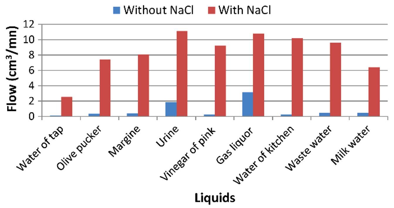
Source: Romdhane ben slama/ Production of Hydrogen by Electrolysis of Water: Effects of the Electrolyte Type on the Electrolysis Performances/ Computational Water, Energy, and Environmental Engineering 02(02):54-58, January 2013/ DOI:10.4236/cweee.2013.22006/ Open Access This is an Open Access article is distributed under the terms of the Creative Commons Attribution 4.0 International (CC BY 4.0)
In 2019, scientists came up with a simple and efficient strategy for the light harvesting component of decoupling III-V-based photoelectrodes from the electrolysis part which could eliminate parasitic light absorption, reduce the cost, and enhance the stability without any compromise in efficiency. The monolithically integrated photoelectrochemical cell was produced by an epitaxial lift-off and transfer of inversely grown In GaP/GaAs to a robust Ni-substrate. The resultant photoanode showed an STH efficiency of ~9% with stability ~150 h. Moreover, with the ability to access both sides of the device, a fully-integrated, unassisted-wireless “artificial leaf” system with an STH efficiency of ~6% was constructed. The excellent efficiency and stability were achieved by the light harvesting/catalysis decoupling scheme, which concurrently improved the optical, electrical, and electrocatalytic characteristics.
Image: Decoupling optical absorption and electrocatalysis. a The typical monofacial PEC device design, in which all functionalities, such as the surface protection layer and electrocatalyst, are integrated on top of the light harvesting side, whereas the bottom side is only used for the electrical connection. The opaque catalytic reflection (Rc) and protection layer reflection (Rp) significantly block light absorption in current monofacial PEC devices. b Our novel, light-decoupled device, in which the light harvesting component is decoupled from the surface protection and electrocatalysis functions. c Schematic illustration of the steps involved in the ELO and transfer processes to fabricate the integrated InGaP/GaAs tandem photoanode on a flexible substrate for PEC water splitting. d, e A wafer-scale inversely grown InGaP/GaAs on single crystalline GaAs substrate before (d) and after (e) ELO and transfer onto a flexible Ni carrier wafer. f Cross-sectional TEM image of the transferred tandem photoanode on the Ni substrate
Source: Purushothaman Varadhan, Hui-Chun Fu, Yu-Cheng Kao, Ray-Hua Horng, Jr-Hau He/ An efficient and stable photoelectrochemical system with 9% solar-to-hydrogen conversion efficiency via InGaP/GaAs double junction/ Nature Communications volume 10, Article number: 5282 (2019), 21 November 2019/ doi.org/10.1038/s41467-019-12977-x/ Open Access This is an Open Access article is distributed under the terms of the Creative Commons Attribution 4.0 International (CC BY 4.0)
The new hydrogen production system has many advantages: The unique feature of the system is that it uses a “SHAREDCELL” between fuel cell cathode and electrolyser anode. This enables the fuel cell cathode electrolyte (Fe3+) to self-regenerate by the anode of electrolyser and simultaneously by oxygen in the air. Therefore, glucose present in electrolysis cell can be effectively converted to pure H2 gas at a low temperature of 85°C by self-powered electric energy. Also, a high hydrogen production rate of 0.0432 mL/cm3/min (or 62.2 m3 H2/m3/d) depending on the electrolysis cell volume can be achieved in the device.
Although only glucose was tested in this study, the scientists believe that based on previous research their device is also suitable for many raw biomasses, such as starch, cellulose, grass and wood powders without having to chemically pre-treat and purify the material. This has the advantage that it would also significantly reduce the feedstock cost.
By the Editorial Board
Research Laboratory news
Electrolytic Process to Convert Glucose to Hydrogen
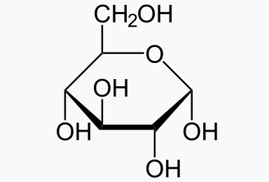
Sourse: NEUROtiker, Public Domain